

Air Conditioning
A320 Air Conditioning System Basics | Pack, Mix & Ram Air Explained
Oct
Just like your home climate control, the A320’s air conditioning system keeps you comfortable at 35,000 feet, but with far more complexity. You’ll find this system manages three independent cabin zones—cockpit, forward, and aft—using two powerful air conditioning packs that transform hot bleed air into cool, breathable atmosphere. Your aircraft intelligently blends this conditioned air with recirculated cabin air through a mixer unit, while ram air provides emergency ventilation if both packs fail. Understanding how pack flow valves, trim air systems, and temperature controllers work together gives you the knowledge to interpret ECAM messages during abnormal operations and maintain passenger comfort throughout your flight.
Overview of the A320 Air Conditioning System
Your aircraft’s environmental control begins with understanding how two identical air conditioning packs work in parallel to deliver conditioned air throughout the cabin. Each pack receives high-temperature, high-pressure bleed air from the engines or APU, then processes it through an air cycle machine that dramatically reduces temperature while maintaining proper humidity levels. The beauty of this design lies in its automation—two Air Conditioning System Controllers (ACSCs) continuously monitor and adjust pack output, trim air mixing, and zone distribution without requiring constant pilot input during normal operations.
What makes this system particularly effective is its ability to balance efficiency with comfort across varying flight phases. During cruise, you’re typically operating with both packs on, blending their output with recirculated cabin air in the mixer unit to reduce bleed air demand and improve fuel efficiency. On the ground with the APU running, a single pack can adequately condition the entire aircraft, though you’ll notice slightly reduced flow rates. The system’s intelligence extends to automatic protection features—pack flow control valves will close during engine start to preserve pneumatic pressure for the starter, and they’ll shut down immediately if overheating is detected, preventing potential damage to downstream components.

A320 Basics, Limitations & SOPs
Complete A320 study guide by an Airbus pilot & instructor.
Clear systems, logic & SOPs.
PDF • 365 pages • Lifetime updates
System Structure
The physical architecture follows a logical flow from source to distribution. Hot bleed air enters each pack at approximately 200°C, passes through primary and secondary heat exchangers cooled by ram air, undergoes compression in a compressor driven by the turbine, and finally expands through that same turbine to achieve temperatures as low as 5°C at the pack outlet. A water separator removes condensation formed during this cooling process, preventing ice crystals from entering the cabin distribution system. Your pack flow control valves—pneumatically operated but electrically commanded by the ACSCs—regulate the volume of air entering each pack based on the selected flow rate: LO, NORM, or HI.

Downstream of the packs, the mixer unit serves as the central collection point where cold pack air combines with recirculated cabin air and hot trim air before distribution. This mixed air feeds into a network of ducts that route to your three independently controlled zones. Hot air for temperature trimming is tapped upstream of the packs and regulated by a dedicated pressure regulating valve controlled by ACSC 1. Each zone—cockpit, forward cabin, and aft cabin—receives its temperature-adjusted air through individual trim air valves that add precise amounts of warm air to the cold pack supply, allowing you to maintain different temperatures in each area based on passenger and crew preferences.
Zones of Control
Your cockpit zone operates independently from the cabin, giving you direct temperature control via the AIR COND panel overhead. The forward cabin zone typically extends from the cockpit bulkhead to approximately row 12, while the aft cabin zone covers the remaining passenger area to the rear pressure bulkhead. Each zone has its own dedicated trim air valve that modulates the mix of cold and hot air—when you rotate a temperature selector to a warmer setting, the corresponding ACSC commands that zone’s trim valve to open further, introducing more hot air into the distribution duct for that specific area.
This zonal independence means your flight deck can be at 22°C while the forward cabin maintains 24°C and the aft cabin sits at 20°C, all simultaneously. The ACSCs continuously compare actual zone temperatures (measured by multiple sensors in each area) against your selected targets, making micro-adjustments to trim valve positions every few seconds. Cabin crew have override capability through the Flight Attendant Panel (FAP), allowing them to adjust cabin zone temperatures within a ±2.5°C range from your cockpit settings—this prevents conflicting temperature commands while still giving them flexibility to respond to passenger comfort requests during service.
During normal operations, the system maintains remarkable precision, typically holding zone temperatures within ±1°C of your selected value. This precision depends on adequate pack flow and proper trim air pressure, which is why degraded modes may limit temperature control range even though ventilation continues. You’ll notice that zone temperature changes aren’t instantaneous—the system requires several minutes to stabilize after adjustment due to the thermal mass of cabin#
Air Conditioning Packs
Your A320’s air conditioning packs serve as the heart of the entire cooling process, transforming hot bleed air into precisely conditioned air suitable for cabin distribution. Each pack operates independently and can supply the entire aircraft if needed, though both typically run simultaneously during normal operations. Located in the belly fairing beneath the fuselage, these packs process bleed air at temperatures that can exceed 200°C and reduce it to approximately 10-15°C at the pack outlet. The pack flow control valve at each pack’s inlet regulates the volume of air entering the system, with three selectable flow rates: LO, NORM, and HI, determined automatically by the ACSCs based on factors like aircraft configuration, flight phase, and engine bleed source.
When you select a pack to ON via the overhead panel, you’re initiating a sophisticated cooling cycle that relies on both thermodynamic principles and ram air assistance. The pack flow control valves are pneumatically operated but electrically controlled, meaning they use bleed air pressure for actuation while receiving commands from the ACSCs. During critical phases like engine start, these valves automatically close to preserve bleed air for the starter, then reopen once the start sequence completes. You’ll also notice automatic closure if a pack overheat is detected on the ground, or if you activate the fire or ditching pushbuttons—safety features designed to isolate the packs from potentially hazardous bleed air sources or prevent water ingress during an emergency water landing.
Functionality and Operation
The operational principle behind your packs is the air cycle refrigeration system, also known as the bootstrap cycle. Hot bleed air first enters the primary heat exchanger where ram air—drawn in through the ram air inlet and accelerated by the ram air fan—provides initial cooling. From there, the air flows to a compressor section within the pack turbine, where compression raises both pressure and temperature again. This seemingly counterintuitive step is imperative because the subsequent cooling in the main heat exchanger becomes more effective with the increased pressure differential. After passing through the main heat exchanger with additional ram air cooling, the air reaches the turbine section where rapid expansion occurs, dropping the temperature dramatically—often to near freezing levels. This expansion process extracts energy from the air, which drives the compressor and ram air fan, creating a self-sustaining cycle that requires no external power beyond the initial bleed air supply.
Your pack’s outlet temperature is continuously monitored and regulated to prevent icing and ensure optimal mixing downstream. If the pack outlet temperature drops below approximately 0°C, the pack flow control valve modulates to reduce airflow and prevent ice formation in the water separator. The ACSCs constantly adjust pack operation based on inputs from multiple temperature sensors, cabin demand, and selected flow rates. During ground operations with the APU supplying bleed air, you’ll typically see reduced pack performance since APU bleed pressure is lower than engine bleed—this is why the HIGH flow setting exists, compensating for reduced bleed availability during single-pack operations or APU-only configurations. Each pack can deliver up to 1,100 kg/hour of conditioned air at maximum flow, sufficient to maintain pressurization and temperature control even with one pack inoperative.
Components of the Packs
Each pack assembly contains several integrated components working in precise coordination. The primary heat exchanger serves as the first cooling stage, utilizing ram air to reduce incoming bleed air temperature before compression. The compressor-turbine unit forms the mechanical heart of the pack, with both components mounted on a common shaft—the turbine’s expansion energy directly drives the compressor and the ram air fan, eliminating the need for external power. Following the turbine, you’ll find the water separator, an often-overlooked but imperative component that removes moisture condensed during the cooling process. This water extraction prevents ice formation in downstream ducting and ensures the air delivered to your cabin maintains appropriate humidity levels. The secondary heat exchanger (main heat exchanger) provides the most significant cooling effect, positioned between the compressor and turbine to maximize the temperature drop during expansion.
Temperature sensors are strategically positioned throughout each pack to provide the ACSCs with real-time data for regulation and fault detection. Pack outlet temperature sensors monitor the#
Temperature Control Mechanisms
Your ability to maintain precise temperature control across the A320 cabin relies on a sophisticated interplay between the Air Conditioning System Controllers (ACSCs) and a network of trim air valves. The ACSCs continuously monitor cabin temperatures through sensors located in each zone, comparing actual readings against your selected target temperatures from the overhead AIR COND panel. When deviations occur, these controllers send electronic signals to modulate the trim air valves, which adjust the ratio of hot air to cold air entering each zone. This closed-loop system operates independently for each of the three zones, ensuring that passenger comfort in the aft cabin doesn’t compromise cockpit conditions or vice versa.
The precision of this system becomes apparent when you consider that temperature adjustments can be made in increments as small as 0.5°C, allowing for fine-tuned control that responds to varying passenger loads, solar heating, and operational phases. During cruise, for example, your system automatically compensates for the extreme cold outside (-55°C at typical cruise altitudes) by carefully blending warm bleed air with pack-cooled air. The ACSCs also account for heat generated by passengers, galley equipment, and avionics, making real-time adjustments to maintain your selected temperature within ±1°C under normal operating conditions.
| Temperature Control Components | Function and Specifications |
|---|---|
| Air Conditioning System Controllers (ACSCs) | Two redundant digital controllers managing all temperature regulation logic; ACSC 1 controls hot air valve, both monitor zone temperatures |
| Temperature Sensors | Multiple sensors per zone (cockpit, forward cabin, aft cabin) providing continuous feedback to ACSCs |
| Trim Air Valves | Three electrically-controlled pneumatic valves (one per zone) that modulate hot air flow for precise temperature control |
| Temperature Selectors | Located on overhead AIR COND panel; allow pilot selection from 18°C to 30°C per zone |
| Flight Attendant Panel (FAP) | Enables cabin crew to adjust cabin zone temperatures within ±2.5°C of pilot-selected values |
| Hot Air Pressure Regulating Valve | Controlled by ACSC 1; regulates pressure of hot air supplied to trim air system, typically maintains 5-10 PSI above cabin pressure |
Role of Trim Air Valves
Trim air valves serve as the final control point in your temperature management system, acting as precision mixing devices that blend hot bleed air with the cold air output from your packs. Each of the three zones—cockpit, forward cabin, and aft cabin—has its own dedicated trim air valve, which receives hot air tapped from upstream of the packs before the air undergoes the cooling cycle. When your ACSC determines that a zone requires warming, it opens the appropriate trim air valve proportionally, allowing hot air (typically around 200°C before regulation) to bypass the cooling packs and mix directly with the cooled pack output. This mixing occurs in the distribution ducts just before air enters each zone, providing immediate temperature response without affecting the other zones.

The sophistication of your trim air valve system becomes evident during asymmetric heating scenarios. Consider a situation where direct sunlight heats the cockpit while passengers in the aft cabin remain comfortable—your system will automatically close or restrict the cockpit trim air valve while maintaining normal operation in the cabin zones. The valves themselves are pneumatically actuated but electrically controlled, meaning they fail in the closed position if electrical power is lost.
The Mixing Unit
Once your packs have delivered their cooled, conditioned air, that air doesn’t go directly to the cabin—it first enters the mixing unit, which serves as the central blending hub for all air sources feeding your aircraft’s environmental system. This component combines fresh air from both packs with recirculated cabin air drawn from the cabin by extraction fans, creating an optimized mixture that balances air quality with system efficiency. By blending approximately 50% fresh air with 50% recirculated air during normal cruise operations, the mixing unit significantly reduces the bleed air demand on your engines, which translates to improved fuel efficiency and lower operating costs.

Your mixing unit also accommodates additional air sources depending on operational conditions. When you’re on the ground with engines off, low-pressure ground air from a ground cart can be introduced into the mixer to maintain cabin ventilation without relying on the APU. Similarly, if you activate the RAM AIR system during an emergency, external ram air flows through the mixer to provide ventilation when both packs have failed. The mixing unit’s design ensures that regardless of which air sources are active, the blended output maintains consistent pressure and temperature characteristics before distribution to your three cabin zones, making it an important bridge between air generation and air delivery.
Air Blending Process
Inside the mixing unit, conditioned air from your left and right packs enters through dedicated inlets and meets with recirculated cabin air that has been filtered and drawn back into the system. The recirculation fans, which are electrically powered, continuously pull cabin air through HEPA-grade filters that remove particulates, odors, and contaminants before reintroducing this air into the mixer. This blending process happens continuously and automatically—
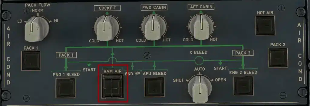
Emergency Ventilation with RAM AIR
When your aircraft experiences dual pack failure or requires immediate smoke evacuation, the RAM AIR system serves as your backup ventilation solution. This system relies entirely on aircraft forward motion to force external air into the cabin through a dedicated ram air inlet located on the forward fuselage. Unlike the sophisticated pack cooling cycle, ram air ventilation is purely mechanical—your airspeed creates the pressure differential needed to push fresh air through the mixing unit and into your cabin zones. You’ll find the RAM AIR pushbutton on your overhead AIR COND panel, typically guarded to prevent inadvertent activation during normal operations.
The system’s effectiveness depends heavily on your flight profile and altitude. At higher airspeeds and lower altitudes, ram air provides adequate ventilation flow, but as you climb or slow down, the available pressure decreases significantly. This is why ram air ventilation works best below 10,000 feet where differential pressure naturally remains lower and your indicated airspeed provides sufficient dynamic pressure. Your flight manual specifies minimum speed requirements for effective ram air operation, and you should plan your descent accordingly if you’re forced to rely on this emergency system for an extended period.
Activation and Functionality
Pressing the RAM AIR pushbutton initiates a sequence that depends entirely on your current pressurization state and mode selection. If your differential pressure reads below 1 PSI and your pressurization system is in AUTO mode, the outflow valve automatically opens approximately 50% to allow ram air to enter the cabin. This partial opening creates a balance between ventilation needs and maintaining some residual pressurization. The system’s logic prevents ram air inlet opening if Δp exceeds 1 PSI because forcing external air into a pressurized cabin could create structural stress and rapid decompression risks. You’ll notice the RAM AIR pb light illuminates when the inlet valve actually opens, confirming that external air is flowing into your mixer unit.
Your pressurization mode selection directly affects ram air functionality in ways you need to anticipate. In MANUAL mode, even with Δp below 1 PSI, the outflow valve will not open automatically—you must manually position it to allow ram air flow. This design prevents unexpected pressurization changes when you’re already managing cabin altitude manually during abnormal situations. Additionally, if the DITCHING pushbutton is pressed, the ram air inlet remains closed regardless of your RAM AIR pb selection to prevent water ingestion during a water landing scenario. The same closure occurs if differential pressure rises above 1 PSI after initial activation, protecting your cabin structure from overpressurization conflicts.
Operational Procedures
Your immediate action when activating ram air should include verifying your current altitude and planning a descent profile that maximizes system effectiveness. Descend to 10,000 feet or below as soon as operational conditions permit, as this altitude provides optimal ram air performance while keeping you in breathable atmosphere without supplemental oxygen for passengers. Maintain an airspeed that generates sufficient dynamic pressure—typically your normal cruise speed or higher if turbulence and structural limits allow. You should also coordinate with ATC for priority handling, as your ventilation-limited condition may require direct routing and expedited descent clearances that deviate from standard procedures.
Monitor your cabin altitude closely through the ECAM PRESS page, watching for any upward trend that indicates insufficient ram air flow. If cabin altitude begins climbing above 10,000 feet despite ram air activation, you must don oxygen masks immediately and consider this a time-critical emergency requiring the fastest practical descent. Your ECAM will guide you through associated procedures, but you should independently verify that both packs remain failed, the ram air inlet is actually open (indicated by the pb light), and your outflow valve position allows adequate airflow. Cross-check your airspeed and altitude against the ventilation requirements in your QRH, as these parameters directly determine whether ram air can sustain your cabin environment.
During extended ram air operations, you’ll need to manage passenger comfort expectations and brief your cabin crew on the situation. Ram air provides ventilation only—no temperature control, no humidity management, and no filtration beyond basic inlet screening. Your cabin temperature
Redundancy and Safety Features
Your A320’s air conditioning system incorporates multiple layers of redundancy to ensure that cabin comfort and safety are maintained even when components fail. The dual-pack architecture means that if one pack experiences a malfunction or is manually shut down, the remaining pack can supply conditioned air to all three cabin zones, though at a reduced flow rate. Pack flow automatically increases to HIGH when operating on a single pack, compensating for the loss of the other unit. This design philosophy extends throughout the system—from the two independent ACSCs that manage temperature control logic to the separate trim air valves for each zone, ensuring that a single point of failure never compromises your ability to maintain pressurization and ventilation.
Beyond component duplication, the system includes automatic protective shutoffs that prevent dangerous conditions from developing. Hot air pressure regulating valves close immediately if duct overheat is detected, protecting against potential fire hazards from uncontrolled hot bleed air. Similarly, pack flow control valves automatically close during engine start sequences to prevent compressor stalls, and will also shut if the ditching pushbutton is pressed, sealing the aircraft against water ingress during an emergency water landing. These interlocks work silently in the background, but they represent thoughtful engineering that prioritizes your safety during both normal operations and emergency scenarios.
System Failover Mechanisms
When you experience a pack failure in flight, the system doesn’t simply alert you and wait for manual intervention—it automatically reconfigures to maintain cabin conditioning. The remaining operational pack transitions to HIGH flow mode without crew input, and the ACSCs redistribute temperature control responsibilities across the available resources. You’ll notice an ECAM message indicating the pack status, but the cabin environment typically remains stable enough that passengers may not even detect the change. This seamless transition is possible because each pack is independently supplied with bleed air and can operate across the full range of flight conditions, from ground operations with APU bleed to high-altitude cruise with engine bleed.
The ACSC failover logic operates with similar intelligence. If ACSC 1 fails, ACSC 2 immediately assumes control of all temperature regulation functions, including management of the hot air pressure regulating valve (normally controlled by ACSC 1) and all three zone trim air valves. Your cockpit indications may show a degraded mode, and you might lose some fine-tuning capability, but basic temperature control continues without interruption. In the rare event that both ACSCs fail simultaneously, the trim air valves default to a preset position that provides a reasonable cabin temperature, and pack operation continues in a simplified mode. This degraded state still delivers conditioned air—it just won’t respond to your temperature selector adjustments.
Role of Air Conditioning System Controllers (ACSCs)
Your two Air Conditioning System Controllers serve as the digital brains behind temperature regulation and system monitoring. ACSC 1 typically handles the hot air pressure regulating valve and cockpit zone trim valve, while ACSC 2 manages the forward and aft cabin trim valves—but this division of labor is flexible. These controllers continuously monitor cabin temperature sensors, compare actual temperatures against your selected targets on the AIR COND panel, and modulate trim air valve positions up to 100 times per second to maintain precise climate control. They also monitor system health parameters, generating ECAM messages when temperatures exceed limits or when valve positions don’t match commanded settings.
The ACSCs communicate with each other via the aircraft’s digital data buses, sharing sensor information and system status to coordinate their actions. This cross-talk enables the automatic failover capability that makes single-controller failures nearly transparent to you and your passengers. Each controller independently monitors critical safety parameters—duct overheat conditions, pack outlet temperatures, and trim air valve feedback—and can command protective shutdowns even if the other controller has failed. This dual-monitoring architecture means that no single electronic failure can result in an undetected overheat condition, providing an additional safety layer beyond the mechanical thermal fuses that serve as last-resort protection.
Conclusion
Now that you’ve explored the A320 air conditioning system in detail, you should have a solid understanding of how the packs, mixer unit, and temperature control work together to maintain your cabin environment. You’ve seen how bleed air enters the system, gets cooled through the air cycle machine, and is intelligently distributed across your three cabin zones with precision control from the ACSCs. You’ve also learned how the system protects itself through automatic valve closures, redundant controllers, and emergency ventilation options like the RAM AIR system. This knowledge equips you to interpret system behavior during normal operations and recognize when degraded modes are active.
As you continue your studies or daily operations with the A320, you’ll find that understanding these air conditioning basics enhances your overall systems knowledge and situational awareness. You now know what’s happening behind the scenes when you adjust a temperature selector, why pack flow changes during different flight phases, and how your aircraft maintains comfort even when one component fails. Whether you’re troubleshooting an ECAM message, responding to abnormal situations, or simply ensuring passenger comfort, your grasp of these fundamentals will serve you well throughout your aviation career.
Learn more about Airbus A320 Systems.