

Airbus A320, ECAM
Airbus A320 Switching Panel Explained: Functions, Logic & Layout

Oct
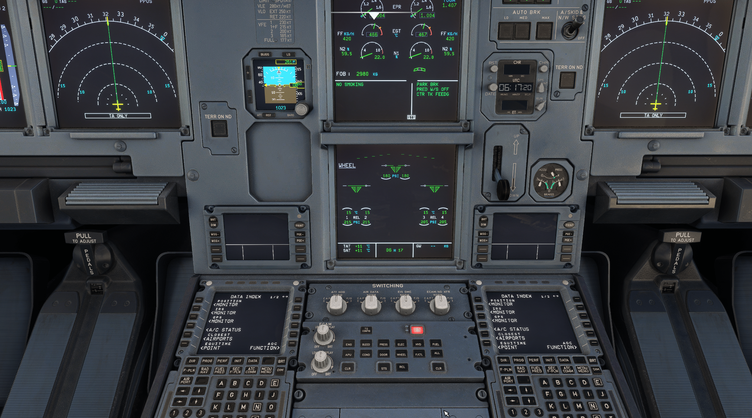
Understanding the A320 Electronic Instrument System (EIS)
The EIS combines the Electronic Flight Instrument System (EFIS) and the Electronic Centralized Aircraft Monitor (ECAM). There are six identical LCD Display Units (DUs): two PFDs, two NDs, and two ECAM displays (E/WD and SD). Three identical DMCs act as data concentrators that feed these displays.
| Display Unit | Role | Default Source |
|---|---|---|
| Captain PFD | Primary flight indications | DMC1 |
| Captain ND | Navigation display | DMC1 |
| F/O PFD | Primary flight indications | DMC2 |
| F/O ND | Navigation display | DMC2 |
| E/WD | Engine and warnings | DMC3 |
| SD | System pages and status | DMC3 |
Under normal conditions DMC1 powers the captain’s side, DMC2 the first officer’s side, and DMC3 both ECAM displays.
If one computer or display fails, the switching panel lets the crew reroute signals to maintain critical awareness without relying solely on automatic reconfiguration.

A320 Basics, Limitations & SOPs
Complete A320 study guide by an Airbus pilot & instructor.
Clear systems, logic & SOPs.
PDF • 365 pages • Lifetime updates
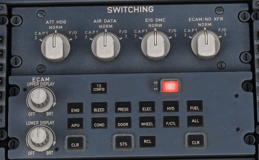
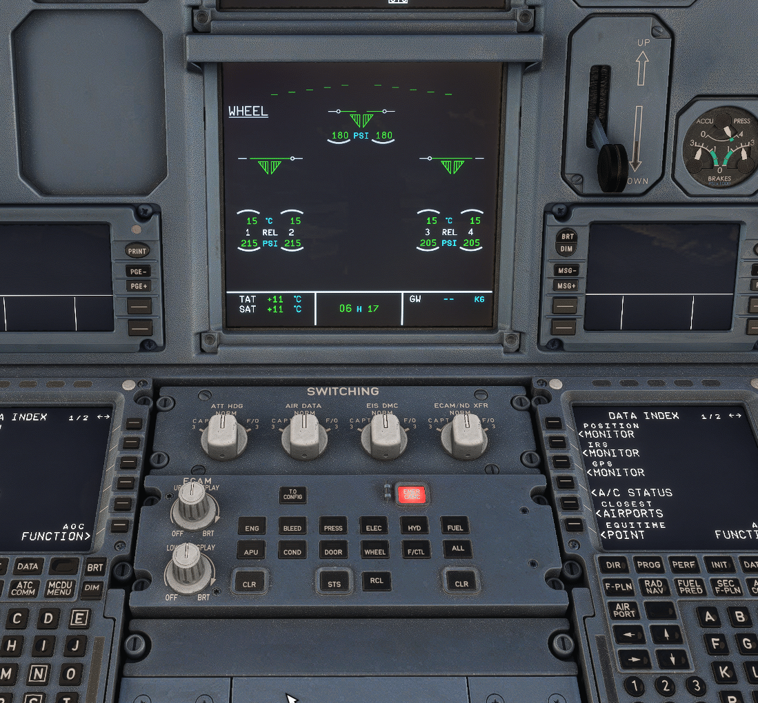
Layout of the A320 Switching Panel (Annotated)
The switching panel sits on the pedestal beneath the ECAM control panel. It comprises four rotary selectors and, depending on fit, a PFD/ND transfer pushbutton. All selectors are spring-loaded to NORM.
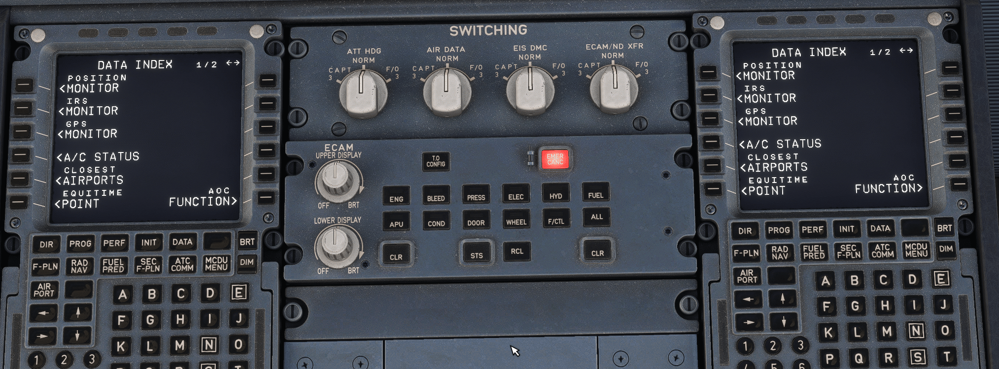
| Selector | What It Controls | Normal Position | When to Use Reversion |
|---|---|---|---|
| EIS DMC | Which DMC drives the captain or F/O displays | NORM | Set to CAPT 3 or F/O 3 if DMC1 or DMC2 fails to feed that side from DMC3 |
| ATT/HDG | Inertial Reference (IR) data source selection | NORM | Select CAPT 3 or F/O 3 if an IR fails; cross-check with standby attitude |
| AIR DATA | Air Data Reference (ADR) source selection | NORM | Select CAPT 3 or F/O 3 if an ADR fails; confirm airspeed/altitude validity |
| ECAM/ND XFR | Transfers ECAM indications to an ND | NORM | Use if an ECAM DU fails so the crew can still see E/WD or SD pages |
| PFD/ND XFR (if installed) | Swaps PFD and ND on the same side | Out | Temporary reconfiguration to prioritize essential symbology |
Functions of Each Selector (Detailed)
EIS DMC Selector
If the captain’s or F/O’s displays go blank due to a DMC fault, use the EIS DMC selector to switch that side to DMC3. Expect momentary ECAM reconfiguration while DMC3 assumes the added load. After restoration, verify that flight guidance cues, map data, and engine indications are coherent and cross-check the standby instruments.
ATT/HDG Selector
This selector changes the source of inertial (IR) data. Use it when an IR fails or is unreliable. Selecting CAPT 3 or F/O 3 assigns the alternate IR to the affected side. Because attitude and heading are foundational to many protections and guidance modes, confirm raw-data agreement before continuing.
AIR DATA Selector
This selector changes the source of air data (ADR). Use it when a side’s ADR is invalid (e.g., flagged airspeed or altitude). After switching, verify that the new air data aligns with standby instruments and that autoflight modes behave as expected, particularly during climb or descent where A/THR targets depend on valid airspeed.
ECAM/ND XFR
If either ECAM display fails, turn ECAM/ND XFR to display the ECAM page on an ND. The affected pilot will momentarily lose the navigation map on that side; coordinate task sharing so the other pilot keeps a navigation display while one ND hosts ECAM.
Failure Scenarios and Crew Actions
DMC Failure (Single and Dual)
Single DMC failure: If DMC1 fails, the captain’s PFD/ND blank. Set EIS DMC to CAPT 3 to feed them from DMC3. If DMC2 fails, set EIS DMC to F/O 3. Expect brief ECAM changes as DMC3 shares tasks. Maintain raw-data monitoring while the system stabilizes.
Dual DMC failures: Prioritize retaining at least one PFD and the E/WD. Use ECAM/ND transfer if needed and review status carefully. Consider workload management: one pilot heads-down for configuration, the other heads-up to fly and communicate.
ADIRS Failures (IR or ADR)
IR failure: Flagged attitude/heading on one side; use ATT/HDG selector to CAPT 3 or F/O 3. Cross-check with standby attitude/heading and confirm FMA modes that rely on valid attitude (e.g., approach modes).
ADR failure: Unreliable airspeed/altitude on one side; use AIR DATA selector to CAPT 3 or F/O 3. Execute unreliable speed procedures if needed until values are validated. Confirm A/THR targets and consider selected/managed mode implications.
ECAM DU Failure
If the E/WD or SD fails, use ECAM/ND XFR so the ND temporarily hosts ECAM. Prioritize the E/WD first for engine and warnings; call for system pages (SD) when time permits. Ensure at least one ND remains available for navigation.
Operational Technique and Best Practices
- Use NORM unless required: The panel is for abnormal situations or maintenance. Avoid casual experimentation in flight.
- Diagnose before switching: Confirm the failing element (DMC vs IR vs ADR vs DU) using ECAM/alerts and instrument flags.
- One change at a time: Make a single, deliberate switch and reassess. Multiple rapid changes increase error risk.
- Cross-check with standby: Use ISIS/standby instruments to validate attitude and airspeed immediately after reconfiguration.
- Brief task sharing: PF flies and communicates; PM performs switching and verifies indications.
- Protect approach phases: Complete any switching before the final approach and never below 1000 ft for CAT II/III.
- Record and report: After landing, make a logbook entry describing the failure and switching actions for maintenance troubleshooting.
A320 Switching Panel in Simulator Training
Type-rating programs stress quick recognition of display loss and disciplined switching. Instructors typically set up DMC1 or IR1 failures and evaluate how the crew prioritizes flight path control, diagnoses the failure, and performs a single, correct selection. Good training also emphasizes when not to switch—such as during stabilized approach inside 1000 ft RA in low-visibility operations.
Example Training Profiles
- DMC1 failure after level-off: PF maintains attitude and heading using the F/O PFD as reference while PM routes CAPT displays to DMC3. Crew confirms correct FMA, raw-data agreement, and restores map if feasible.
- IR1 fault in climb: PF transitions to the unaffected side’s PFD; PM selects ATT/HDG CAPT 3, validates attitude, then resumes normal monitoring.
- SD failure in cruise: PM uses ECAM/ND XFR to call system pages on the ND when required; limits time heads-down and returns ND to map for situational awareness.
Why the Switching Panel Matters
The A320 switching panel embodies Airbus’s redundancy philosophy, ensuring pilots have a reliable way to manage critical functions. This panel provides a straightforward, tactile way to maintain essential displays when automatic logic cannot.
The result is higher resilience against sensor and computer faults, which enhances overall flight safety. With the A320 family, pilots benefit from improved situational awareness and continued access to engine and systems data.
This access supports safe decision-making during all phases of flight, especially in challenging scenarios. The switching panel is an integral part of the flight deck, allowing for effective control over various systems.
For sim pilots using platforms like Microsoft Flight Simulator, understanding the A320 switching panel is crucial for realistic flying experiences. Resources such as Flybywire simulations documentation provide valuable insights into the operation and functionality of the panel.
Additionally, the audio and light indicators on the panel enhance communication of system statuses, making it easier for pilots to respond appropriately. Overall, the A320 switching panel is essential for maintaining operational integrity and safety in the cockpit.
How Airbus Differs from Other Airliners
Compared with designs that keep display reconfiguration almost entirely automatic, Airbus gives the crew direct authority to reassign data paths. The benefit is explicit control when time-critical troubleshooting is required. The trade-off is that pilots must know the implications of each selector and apply them deliberately, with attention to phase of flight and approach minima.
| Function | Airbus A320 | Common Alternative |
|---|---|---|
| Display computer reversion | Manual via EIS DMC switch | Often automated via display processor logic |
| IR/ADR source selection | Manual per side (ATT/HDG, AIR DATA) | Mixed; sometimes automated with limited manual override |
| ECAM/EICAS reversion | Manual ECAM to ND transfer | Often automatic EICAS reversion |
| Approach restrictions | No switching below 1000 ft in CAT II/III | Similar protections exist |
Summary
- The switching panel allows manual reconfiguration of EIS data paths to maintain key indications after failures.
- It includes EIS DMC, ATT/HDG, AIR DATA, and ECAM/ND XFR selectors (plus optional PFD/ND XFR).
- Use sparingly, one change at a time, with standby cross-checks and careful task sharing.
- Do not perform switching below 1000 ft in CAT II/III operations.
- Mastery of this panel is a core competency in A320 abnormal operations and simulator training.
References
- Airbus A320 Flight Crew Operating Manual (FCOM), Indicating/Recording Systems — Switching and Reconfiguration.
- Airbus A320 Airplane Flight Manual (AFM), Abnormal Procedures and Low-Visibility Approach Limitations.
- Airbus A320 Flight Crew Techniques Manual (FCTM), Display management and abnormal operations techniques.
- ATA 31: Indicating/Recording Systems — A320 Electronic Instrument System overview.
Learn more about Airbus A320 Systems.