
Airbus A320, Autoflight System
Airbus A320 Autoflight System (ATA 22) – A Practical, Pilot-Friendly Guide

Dec
Always follow your company SOPs and the applicable Airbus documentation for your aircraft standard.
If you’re using a flight simulator, treat this as conceptual guidance only and match it to the sim’s aircraft version.
A320 Basics, Limitations & SOPs
Complete A320 study guide by an Airbus pilot & instructor. Clear systems, logic & SOPs.
PDF • 365 pages • Lifetime updates
What is the A320 Autoflight System?
functions and key components that: manage the flight plan and aircraft performance, provide lateral and vertical guidance, and
automatically control thrust and trajectory—so the aircraft follows an intended flight profile with fewer manual inputs.
Core outcomes
- Lower routine workload (especially in managed flight)
- More stable speed/vertical profiles when properly configured
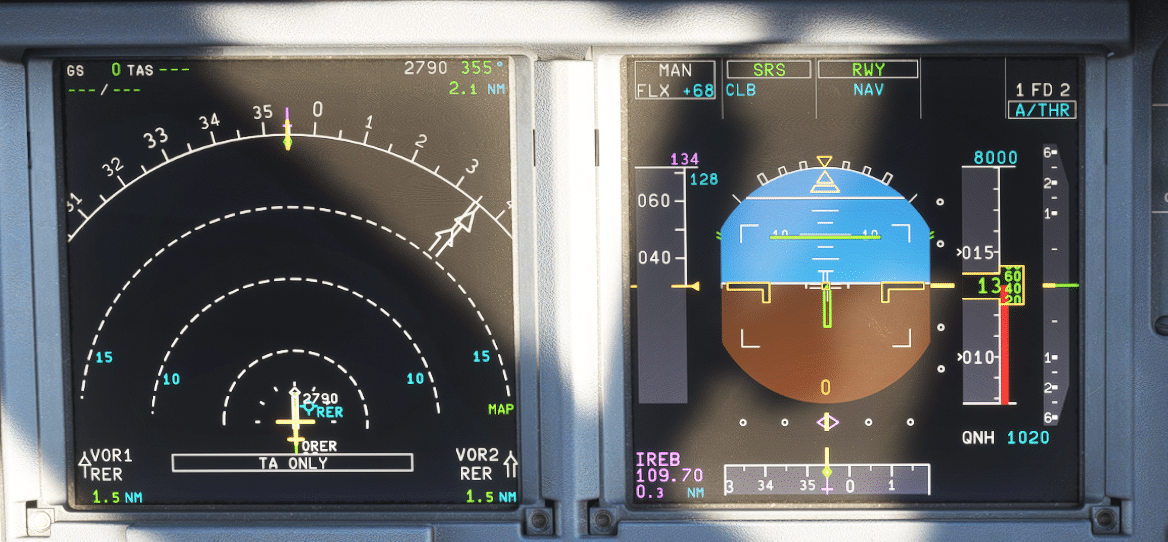
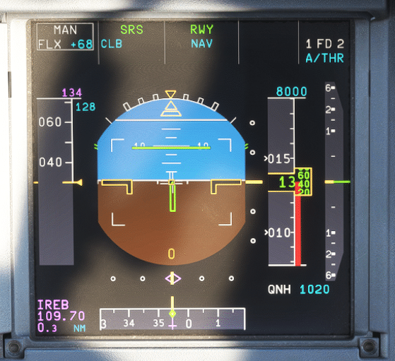
- Mode transparency through the Flight Mode Annunciator (FMA) on the primary flight display
What it’s not
- Not “set-and-forget” automation
- Not immune to incorrect inputs or mode misunderstandings
- Not a replacement for raw data cross-checks when required
A quick “systems map” for the flight deck
the MCDU builds the plan (routes, constraints, waypoints), the FCU on the glareshield is the tactical control panel with each knob acting as a selector, and the PFD/ND show what guidance is doing in real time. The AP/FD and A/THR then drive the aircraft’s aircraft attitude, speed, and flight path.
FMGS Architecture: The Main Building Blocks
two Flight Management and Guidance Computers (FMGCs) (often described as management guidance computers), two MCDUs, one FCU, and two Flight Augmentation Computers (FACs).Together, they perform the computation needed to guide the airplane laterally and vertically using inputs from the aircraft reference system.
1) FMGCs: “Brain” for Flight Management + Flight Guidance
Each FMGC contains two major functional “halves”: Flight Management (FM) (navigation, flight planning, predictions/optimization, display management), and Flight Guidance (FG) (autopilot, FD flight director, and autothrust commands). This is the core of the flight management system.
The FMGCs use inputs such as air data (speed/altitude) and inertial references (via ADIRU) to compute guidance targets.
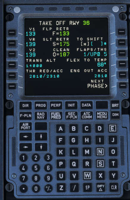
2) MCDU: Where you build and manage the plan
The Multipurpose Control and Display Units (often informally grouped as control display units) are the long-term interface.
Typical tasks include route setup (SID/enroute/STAR/approach/alternate), performance entries, revisions (direct-to, holds, secondary flight plan),
and monitoring pages (F-PLN/PROG/PERF) that help validate the intended flight profile.
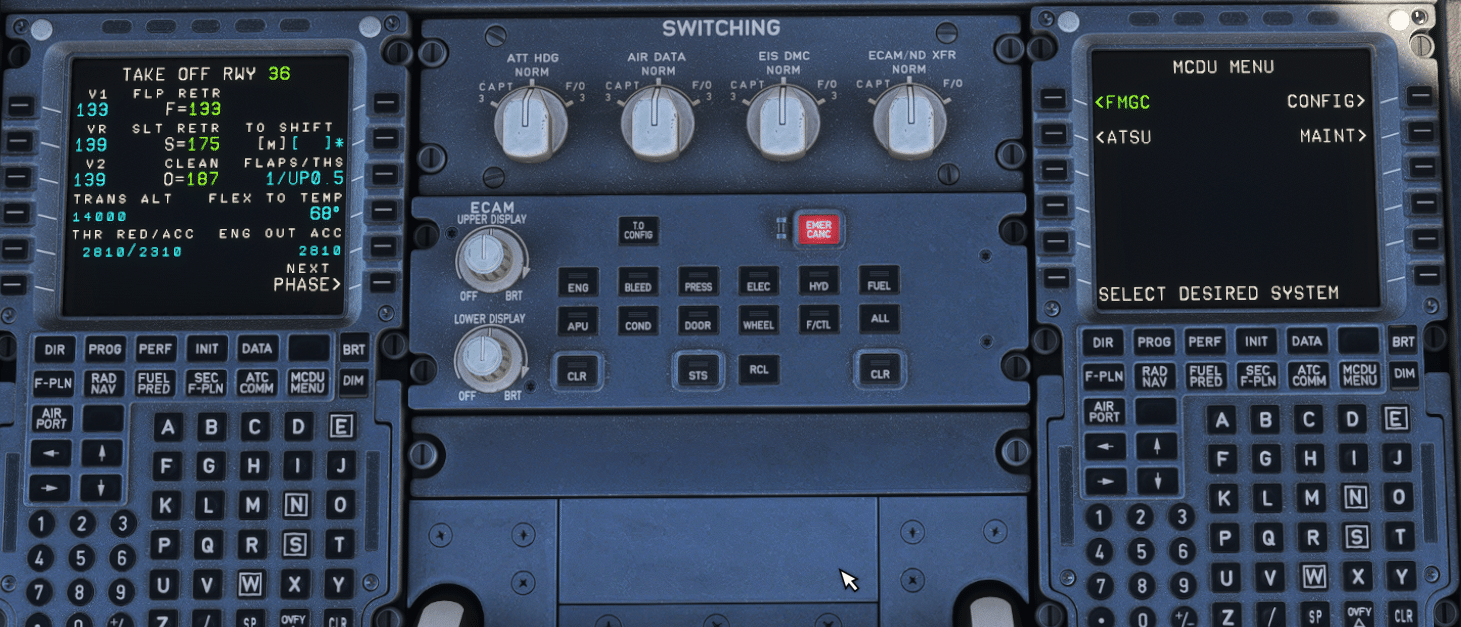
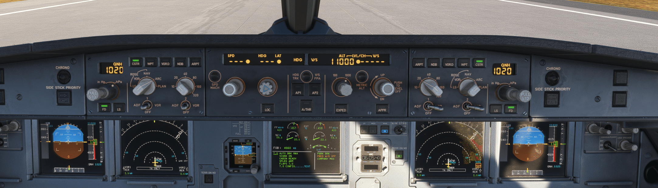
3) FCU: The glareshield control panel (your tactical selector)
The Flight Control Unit (FCU) sits on the glareshield as the main tactical control panel.
It lets you engage/disengage AP and A/THR, and select or manage targets such as speed (airspeed), heading/track, altitude, vertical speed/selected vertical speed, or flight path angle—depending on which knob you turn, push, or pull. This is where the crew commands an active vertical mode (e.g., climb/descent capture logic) in daily operations.
4) FACs: Flight augmentation & yaw functions
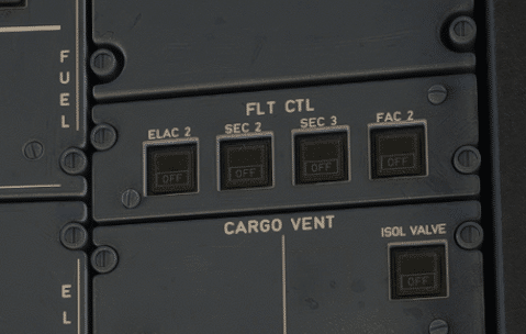
Operational takeaway: Autoflight is distributed: FMGCs do guidance computation, FCU/MCDU provide crew interfaces, and FACs provide augmentation.
All of it relies on trustworthy air data and inertial references (via ADIRU)—which is why cross-checking speed/altitude sources matters.
A320 Basics, Limitations & SOPs
Complete A320 study guide by an Airbus pilot & instructor. Clear systems, logic & SOPs.
PDF • 365 pages • Lifetime updates
Managed vs Selected Guidance: The Airbus Automation Foundation
selected guidance (pilots manually choose a target value—speed, heading, vertical speed, etc.).Both influence the aircraft’s flight path and aircraft attitude.
Managed guidance
- Targets come from the FMGS (route + constraints + aircraft performance)
- FCU windows show dashes for managed targets (except altitude window)
- White dots next to FCU windows indicate managed target use
Selected guidance
- Targets are entered by the pilot using FCU selectors
- FCU windows show the chosen numeric value
- Selected guidance generally takes priority over managed
Push vs Pull: How pilots choose managed/selected
- Push a knob to arm/engage managed guidance for that parameter (e.g., engage NAV from HDG by pushing HDG knob).
- Rotate + Pull a knob to engage selected guidance (e.g., set a speed then pull SPD knob to select it).
- Altitude is special: the altitude window always shows a value selected by the flight crew (not dashes).
Autopilot & Flight Director Modes — and Why the FMA Is the “Truth”
On the A320, modes can be armed, engaged, or disengaged. The Flight Mode Annunciator (FMA) on the primary flight display is your primary reference for what the aircraft is doing right now and what it will do next.
This is true whether you’re flying manually with FD guidance or with the autopilots engaged.
High-value habits
- Announce + confirm every mode change (both PF and PM)
- Always verify: lateral and vertical modes and A/THR status together on the PFD
- During level-offs: confirm whether ALT is capturing the FCU altitude or an altitude constraint (ALT CST logic)
Examples of “what changes when you change one thing”
- If you engage HDG/TRK, guidance no longer follows lateral flight plan constraints; depending on the situation, the vertical logic may revert. Always re-check the vertical mode and the commanded flight path after any lateral change.
- When the system is flying a managed descent path, changing to open descent means “direct to FCU altitude,” typically disregarding altitude constraints – confirm expectations on the FMA and ND constraints, and verify speed/energy via airspeed trends.
FMGS modes of operation (dual / independent / single)
In normal operations, the A320 FMGS runs in dual mode: both FMGCs are synchronized and exchange data, with one acting as master.
Under certain abnormal conditions, the system can revert to independent or single mode. The “master” logic can change depending on which
AP/FD is engaged—so the best habit is: “FMA first.”
Where ILS fits in
Autothrust (A/THR): How the A320 Manages Thrust
Speed/Mach (continuously adjusts thrust to maintain airspeed) and thrust modes (holds a fixed thrust request associated with a mode).
Mode linkage is the key
- When a vertical mode controls the flight path (trajectory), A/THR often operates in SPEED/MACH.
- When a vertical mode uses pitch to maintain speed (common in open modes), A/THR may be in a thrust mode.
(e.g., CL detent), while the system modulates thrust to maintain speed or energy.
Air data, ADIRU, and energy management
Approach & Autoland Basics: What to Expect (and What to Verify)
CAT II/CAT III & automatic landing (conceptual flow)
- Before the approach: set DH (or NO DH if applicable), ensure the approach is properly set up and brief the flight deck plan.
- During interception: arm approach mode, verify approach phase active, engage a second autopilot if available, manage A/THR as required.
- On final:
- Around 350 ft RA: verify LAND annunciation (entering land mode logic).
- Around 30 ft: verify FLARE.
- Around 10 ft: reduce thrust to idle (as per procedure).
- At touchdown: verify ROLL OUT and be ready for rollout steering logic.
- After landing: disconnect autopilot no later than exiting the runway.
“Armed vs engaged” and “capability” indications are not decoration—treat them like checklist items.
How LAND/FLARE/ROLL OUT fit into the mode system
In Airbus logic, LAND, FLARE, and ROLL OUT engage automatically in the right conditions during an autoland sequence.
During rollout, the system supports runway tracking and may coordinate with steering functions such as nose wheel steering—but the crew remains
responsible for monitoring and for timely disconnects as required by procedures.
Monitoring & Common Traps (Practical Tips)
Trap: “I pulled HDG—why did my vertical mode change?”
If you’re no longer on the managed lateral path, some managed vertical behaviors may revert. Always re-check the vertical mode and what it’s targeting after any lateral change—especially if you’re trying to maintain a stable flight path.
Trap: Selected speed that quietly lasts too long
Trap: Surprise constraint capture on level-off
Monitor constraint symbols on the ND and FMA arming so a constraint capture doesn’t feel like a mystery.
Trap: Forceful inputs with AP engaged
The side stick is locked in neutral when the autopilot is engaged; applying force above a threshold can disconnect the AP.
Use standard disconnect methods and confirm the AP state on the FMA.
Simple “mode discipline” checklist
- What is engaged now? (FMA active modes)
- What is armed next? (FMA armed modes)
- What is the aircraft trying to capture? (FCU targets + constraints)
- Is A/THR active/armed? (and does that match the phase and intention?)
- Do my ND/PFD cues match the plan? (track, vertical path, constraint markers)