You’ll encounter the flight path vector, commonly called the “bird,” as one of two primary flying references on your A320’s Primary Flight Display. This symbol appears only when TRK/FPA mode is selected on the Flight Control Unit, providing real-time trajectory information computed from IRS and static pressure data. While the bird offers valuable guidance for approaches and visual circuits, you must understand its limitations – it’s affected by inertial errors up to ±2° and becomes unreliable when altitude information is compromised. Always change attitude first, then reference the bird for optimal flight path management during your operations.
Decoding Flight Path Vector Dynamics
Your A320’s PFD operates with two distinct flying references that fundamentally change how you interpret flight data. The flight path vector responds to inertial reference system data and static pressure information, making it susceptible to errors of up to +/-2° during approaches. Unlike attitude-based flying, the bird shows you where your aircraft is actually going through the air mass, not where the nose is pointing. This distinction becomes critical when wind conditions create significant differences between your aircraft’s heading and actual track over the ground.
Mastering “The Bird” – Airbus A320 Flight Path Vector Explained!
The Role of the Flight Path Vector on the PFD
When you select TRK/FPA on your FCU, the bird becomes your primary flight reference, replacing traditional attitude-based flying with track and flight path angle parameters. The symbol’s position relative to your fixed aircraft symbol immediately reveals wind direction and strength – if the bird drifts right, you’re experiencing wind from the left. During final approach, this relationship helps you anticipate runway positioning before visual contact. The bird’s wings aligned with the horizon indicate level flight, while positioning the tail on the blue track index maintains your desired ground track.
Transitioning Between TRK/FPA and HDG/VS Modes
Mode transitions occur automatically during specific flight phases, with the system prioritizing safety over pilot preference. Upon TOGA selection during go-around, the bird automatically disappears regardless of your previous selection, as dynamic maneuvers require immediate attitude response rather than trajectory-based references. The flight director bars restore to SRS/GA TRACK modes, shifting your reference from ground-stabilized trajectory back to air-stabilized flight path management.
Understanding when each mode excels prevents dangerous misinterpretation of flight data. TRK/FPA mode stabilizes your trajectory relative to the ground, making it ideal for approaches and cruise flight where precise ground track matters. However, HDG/VS mode stabilizes relative to the air mass, providing immediate attitude feedback crucial for dynamic maneuvers. During takeoff, your sidestick inputs create immediate attitude changes that you can monitor directly, while the bird’s trajectory indication would lag behind actual aircraft response. This lag becomes particularly hazardous during go-around procedures where split-second attitude adjustments determine climb performance and obstacle clearance.
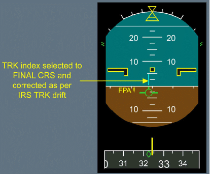
Understanding when to deploy the flight path vector versus attitude reference separates proficient A320 pilots from those who struggle with mode confusion. Dynamic maneuvers like takeoffs and go-arounds demand attitude reference due to the immediate response required, while stabilized flight phases benefit from FPV guidance. Visual circuits showcase the bird’s versatility – positioning its wings on the horizon maintains level flight on downwind legs, while aligning the tail with the blue track index ensures precise tracking. The 3-degree approach path appears when the bird’s tail sits immediately below the horizon with its bottom just above the 5-degree nose-down marker.
Navigating Dynamic Maneuvers: When to Rely on Attitude
Sidestick inputs produce immediate attitude changes that you can monitor directly and accurately during dynamic phases. Go-around procedures exemplify this principle – the inevitable lag between nose-up input and trajectory response makes attitude reference crucial. The A320’s automation recognizes this limitation: TOGA selection automatically removes the bird and restores flight director bars in SRS/GA TRACK modes, regardless of your previously selected reference. Takeoff scenarios similarly demand attitude reference for the precise control needed during rotation and initial climb.
Harnessing FPV for FPA Guidance during Approaches
Non-precision approaches reveal the FPV’s greatest strength through TRK-FPA flight director coupling. You select inbound track and final descent path angle values on the FCU, then align the FPV symbol within the flight path director symbol for ground-stabilized trajectory guidance. This differs fundamentally from HDG-V/S mode, which provides air-stabilized guidance. Minor corrections maintain accurate approach paths once established inbound, though you must understand the bird indicates flight path angle and track without providing ground-based facility guidance.
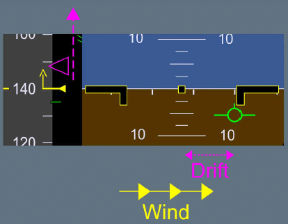
The FPV’s approach utility extends beyond basic guidance to immediate wind awareness and shear detection capabilities. Wind direction becomes instantly apparent through the bird’s position relative to the fixed aircraft symbol – rightward drift indicates left crosswind, while upward movement of the target approach speed symbol warns of headwind gusts. This real-time environmental feedback proves invaluable when approaching minimums, as you’ll know precisely which direction to search for the runway based on wind indication. The combination of FPV with GS MINI protection creates an excellent early warning system for wind shear or downdraft encounters, providing trajectory parameters that quickly alert you to atmospheric disturbances before they become critical.
Mastering Visual Flight Circuits with FPV
Visual circuits benefit significantly from FPV cross-referencing, providing precise trajectory control throughout the pattern. Position the bird’s wings directly on the horizon during downwind legs to maintain level flight, while setting your desired downwind track on the FCU. The bird’s tail alignment with the blue track index on the PFD ensures accurate ground track maintenance despite wind conditions. This technique transforms visual flying from attitude-based guesswork into precise trajectory management, particularly valuable during gusty conditions or unfamiliar airports where ground references may be limited.
Interpreting Downwind Flight and Track Control
Downwind leg precision depends on positioning the bird’s tail precisely on the blue track index while maintaining the wings on the horizon line. Your FCU downwind track setting becomes the reference point, with the FPV providing immediate feedback on actual ground track versus intended path. Wind drift becomes instantly visible as the bird moves away from the track index, allowing for immediate corrections without waiting for ground reference confirmation or compass heading changes.
Aligning Final Approach Techniques for Glide Path Accuracy
Final approach alignment requires positioning the bird’s top tail immediately below the horizon with the bottom above the 5° nose-down marker to achieve a standard 3° glide path. Set your FCU track index to the runway’s final approach course, creating a precise visual reference system. This configuration provides immediate glide path deviation awareness without relying solely on PAPI or ILS guidance systems.
The FPV’s effectiveness during final approach extends beyond basic glide path control, serving as an early warning system for atmospheric disturbances. Downburst detection occurs through rapid bird movement, while wind shear manifests as sudden FPV displacement relative to the fixed aircraft symbol. The bird’s position immediately indicates wind direction – rightward drift signals left crosswind, helping you anticipate runway alignment requirements before visual acquisition. During approach minimums, this wind indication guides your visual search pattern, as you’ll know which direction to look for runway alignment. Target approach speed symbol movement correlates with the bird’s behavior: upward speed target movement combined with bird stability indicates headwind gusts, while bird drift with stable speed targets suggests crosswind components requiring rudder input for track maintenance.
Enhancements to Flight Safety through FPV
The flight path vector transforms hazardous weather encounters from reactive situations into proactive management scenarios. Downburst detection becomes immediate as the bird’s position shifts dramatically relative to your intended trajectory, providing precious seconds for corrective action. Combined with enhanced situational awareness during low-visibility approaches, the FPV delivers real-time feedback on your aircraft’s actual movement through the air mass, enabling you to maintain precise control even when external visual references deteriorate.
Utilizing FPV for Wind Shear and Gust Detection
Wind shear manifestations appear instantly through FPV displacement patterns on your PFD. Headwind gusts trigger upward movement of the target approach speed symbol, while lateral wind shifts cause the bird to drift correspondingly – right drift indicates wind from the left. This immediate visual feedback allows you to anticipate required control inputs before airspeed or altitude deviations become significant, maintaining approach stability during challenging wind conditions.
Integrating GS MINI with FPV for Added Protection
GS MINI protection works synergistically with FPV to create a comprehensive wind shear detection system. The combination provides excellent indication of shears and wind variations during approach phases, where traditional airspeed-based warnings might react too slowly. Your FPV shows trajectory changes while GS MINI prevents dangerous airspeed decay.
This integration becomes particularly valuable during final approach when you’re operating near minimum safe airspeeds. GS MINI automatically increases your target approach speed when detecting windshear conditions, while the FPV simultaneously displays the actual flight path deviation. The dual-system approach means you receive both protective speed management and precise trajectory information, allowing for coordinated responses to windshear encounters. During severe windshear events, GS MINI can command speed increases of up to 15 knots above your selected approach speed, while the FPV shows you exactly how these speed changes affect your actual ground track and descent angle, enabling precise flight path corrections without compromising approach safety margins.
Recognizing Limitations of the Flight Path Vector
The flight path vector, while highly accurate in most conditions, operates within specific technical boundaries that can affect your flight operations. Inertial Reference System errors and static pressure anomalies directly impact the bird’s reliability, making awareness of these limitations necessary for safe operations. Understanding when and why the FPV may provide misleading information helps you make informed decisions about which flight reference to prioritize during different phases of flight.
Your A320’s flight path vector derives its data from the Inertial Reference System, which introduces inherent measurement errors during flight operations. Track errors of up to ±2 degrees commonly occur during approach phases, requiring you to cross-reference with other navigational aids. These inertial errors accumulate over time and distance, particularly affecting long-haul flights where the IRS drift becomes more pronounced, making periodic position updates through GPS or ground-based navigation aids necessary for maintaining accuracy.
Situations That Demand Caution: Altitude Data Reliability
Static pressure system malfunctions directly compromise the flight path vector’s vertical guidance accuracy, as the bird relies on this data for flight path angle calculations. Any altitude information unreliability renders the entire FPV display suspect, requiring immediate transition to attitude-based flight references. Blocked pitot-static ports, system failures, or extreme weather conditions can trigger these scenarios, demanding heightened vigilance during your approach and landing phases.
Altitude data corruption manifests in several critical scenarios that you must recognize immediately. Icing conditions can block static ports, creating false altitude readings that directly feed erroneous data to the flight path vector system. During these events, your FPV may indicate a safe descent angle while the aircraft actually follows a dangerously steep or shallow trajectory. System malfunctions in the Air Data Computer also propagate through to the bird display, creating situations where the symbol appears normal but reflects completely incorrect flight path information. Multiple aircraft incidents have occurred when pilots relied on compromised FPV data during critical approach phases, emphasizing why Airbus mandates immediate reversion to attitude references when any altitude system anomaly occurs. Your standard operating procedures require cross-checking altitude sources and immediately disregarding the bird when discrepancies appear between primary and backup altitude systems.
Summing up
So the Airbus A320’s flight path vector “bird” serves as your primary flight reference when TRK/FPA mode is selected, displaying actual aircraft trajectory rather than attitude. You’ll find it particularly valuable during approaches and visual circuits, where it provides immediate feedback on track and flight path angle relative to the ground. However, you must understand its limitations – the bird relies on IRS data subject to inertial errors and can show track deviations up to ±2°. When using it, you should adjust attitude first, then verify results against the bird’s indication for optimal flight path management.
Frequently Asked Questions
What is the Flight Path Vector (FPV) or "bird" symbol on the Airbus A320 Primary Flight Display?
The Flight Path Vector (FPV), commonly called the "bird," is one of two flying references displayed on the A320's Primary Flight Display (PFD). The bird appears when TRK/FPA mode is selected on the Flight Control Unit (FCU) and serves as the primary flight reference using track (TRK) and flight path angle (FPA) as guidance parameters. Unlike the attitude reference which shows where the aircraft is pointing, the bird indicates the actual trajectory the aircraft is following through the air. The symbol resembles a bird with wings and a tail, providing pilots with immediate visual feedback about their flight path direction and angle relative to the horizon and desired track.
When should pilots use the Flight Path Vector versus the attitude reference, and what are the limitations?
The Flight Path Vector should be used for stabilized flight phases like cruise, approach, and visual circuits, while the attitude reference is preferred for dynamic maneuvers such as takeoff and go-around. The bird is automatically removed during go-around when TOGA is selected because immediate attitude response is needed. The FPV has reliability limitations as it's computed from IRS data and can have inertial errors up to ±2° during approach. It also relies on static pressure information, so if altitude data is unreliable, the bird becomes unreliable too. The general rule when using the bird is to first change attitude, then verify the result by referencing the bird symbol.
How do pilots practically use the Flight Path Vector during different phases of flight?
During approach with FPA guidance, pilots set the desired track and flight path angle on the FCU and align the FPV with the Flight Path Director (FPD) symbol for guidance along a ground-stabilized trajectory. For visual circuits, pilots position the bird's wings on the horizon for level flight on downwind, and align the tail with the blue track index to maintain desired track. On final approach, a standard 3° glide path is indicated when the bird's tail top sits just below the horizon and the bottom sits above the 5° nose-down marker. The bird also provides valuable wind information - its position relative to the fixed aircraft symbol shows wind direction, helping pilots know where to look for the runway during approach minimums.
Airbus A320 flight path vector (bird) explainedYou’ll encounter the flight path vector, commonly called the “bird,” as one of two primary flying references on your A320’s Primary Flight Display. This symbol appears only when TRK/FPA mode is selected on the Flight Control Unit, providing real-time trajectory information computed from IRS and static pressure data. While the bird offers valuable guidance for [...]