

Airbus A320, Hydraulic System
Airbus A320 Hydraulic System Explained: Green, Blue, Yellow, PTU & RAT

Oct
Key Takeaways
- The Airbus A320 has three independent hydraulic systems: Green, Blue and Yellow.
- Normal hydraulic operating pressure is approximately 3,000 psi (207 bar).
- The Green system is normally powered by the Engine 1-driven pump.
- The Blue system is normally powered by an electric hydraulic pump.
- The Yellow system is normally powered by the Engine 2-driven pump and also has an electric pump.
- The PTU transfers hydraulic power between Green and Yellow without transferring hydraulic fluid.
- The RAT provides emergency hydraulic power to the Blue system.
- Hydraulic redundancy helps maintain essential aircraft functions following certain failures.
1. Airbus A320 Hydraulic System Overview
The Airbus A320 family uses three independent hydraulic systems identified by the colors Green, Blue and Yellow. These systems provide hydraulic power to flight-control actuators and other aircraft services, including landing gear, braking, nose-wheel steering, thrust reversers and cargo doors.
Each hydraulic system has its own reservoir, pressure sources and associated components. The systems are physically separated to prevent hydraulic fluid from transferring between circuits.
This architecture provides redundancy. Different hydraulic circuits supply selected flight-control actuators, helping preserve aircraft controllability following a hydraulic system failure.
A320 Hydraulic System Comparison
| System | Normal Power Source | Additional Power Source | Nominal Pressure |
|---|---|---|---|
| GREEN | Engine 1-driven pump | PTU from Yellow | 3,000 psi |
| BLUE | Electric pump | Ram Air Turbine | 3,000 psi normally |
| YELLOW | Engine 2-driven pump | Electric pump and PTU from Green | 3,000 psi |
The Green and Yellow systems are mechanically interconnected by the PTU. The Blue system remains hydraulically independent and is not connected to the PTU.
2. Airbus A320 Hydraulic System Diagram
The following A320 hydraulic system infographic provides a simplified visual overview of the three hydraulic circuits, their normal power sources and their principal aircraft services.
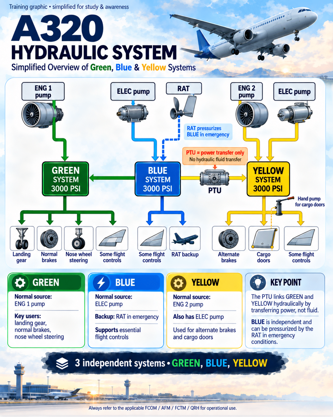
Figure 1. Simplified Airbus A320 hydraulic system overview showing the three independent circuits, normal pressure sources, PTU and emergency RAT backup. Educational illustration only.
Important: The PTU connects only the Green and Yellow systems. It does not connect to the Blue system. The infographic must accurately represent this arrangement before publication.
3. Green, Blue and Yellow Hydraulic Systems Explained
Green Hydraulic System
The Green hydraulic system is normally pressurized by an Engine-Driven Pump (EDP) installed on Engine 1. Its nominal operating pressure is approximately 3,000 psi.
The Green system supplies several important aircraft functions, including:
- Normal landing gear extension and retraction.
- Normal braking.
- Nose-wheel steering.
- Selected primary flight-control actuators and spoilers.
- Engine 1 thrust reverser actuation.
If the Green engine-driven pump becomes unavailable, the PTU may allow hydraulic power from the Yellow system to pressurize Green, provided the applicable system conditions permit.
The Green system does not have a dedicated electric hydraulic pump.
Blue Hydraulic System
The Blue hydraulic system differs from Green and Yellow because it does not have an engine-driven pump. Under normal operating conditions, it is pressurized by an electrically driven hydraulic pump.
The Blue system supplies selected flight-control actuators, including portions of the aileron, elevator and spoiler hydraulic architecture.
In qualifying emergency conditions, the Ram Air Turbine can provide hydraulic power to the Blue system.
Key distinction: The Blue system is completely independent of the PTU. Hydraulic power cannot be transferred between Blue and Green or between Blue and Yellow through the PTU.
Yellow Hydraulic System
The Yellow hydraulic system is normally pressurized by an engine-driven pump installed on Engine 2. It also includes an electrically driven hydraulic pump that can provide pressure when suitable electrical power is available.
The Yellow system supplies aircraft functions including:
- Alternate and parking braking functions.
- Cargo-door hydraulic operation.
- Selected primary flight-control actuators and spoilers.
- Engine 2 thrust reverser actuation.
The Yellow system also incorporates a hand pump used for cargo-door operation under appropriate ground conditions when electrical power is unavailable.
Through the bidirectional PTU, Yellow can receive hydraulic power from Green or provide hydraulic power to Green.
4. Airbus A320 Power Transfer Unit (PTU)
The Power Transfer Unit (PTU) is a bidirectional hydraulic motor-pump assembly that allows hydraulic power to be transferred between the Green and Yellow systems without transferring hydraulic fluid.
The PTU is a major component of the A320 hydraulic redundancy architecture.
How Does the A320 PTU Work?
When a sufficient pressure differential develops between Green and Yellow, and PTU operation is permitted, the PTU can operate automatically.
The normal operating threshold is approximately 500 psi pressure differential.
For example, if the Green system is pressurized normally while Yellow pressure is insufficient, hydraulic energy from Green can drive the PTU motor. The mechanically coupled pump then generates hydraulic pressure in Yellow.
The reverse process is also possible, allowing Yellow to provide hydraulic power to Green.
Important: The PTU transfers mechanical power, not hydraulic fluid. The two hydraulic circuits remain physically separated.
Why Does the A320 Make a Barking Noise?
The characteristic barking or growling sound heard on some Airbus A320 aircraft during ground operations is commonly associated with PTU operation.
The sound results from hydraulic pressure fluctuations and the operation of the PTU motor-pump assembly. It may be heard during engine-start or taxi phases when Green and Yellow hydraulic pressures differ, subject to the applicable PTU inhibition logic.
Does the PTU Always Operate at a 500 psi Differential?
No. Although approximately 500 psi is the normal differential threshold, PTU operation is subject to automatic inhibition and system conditions.
Specific ground conditions, cargo-door operation and certain abnormal hydraulic conditions can affect PTU availability. Pilots must refer to the applicable Airbus FCOM for exact operating and inhibition logic.
5. Airbus A320 Ram Air Turbine (RAT)
The Ram Air Turbine (RAT) is an emergency power device that uses airflow to drive a hydraulic pump. On the conventional A320 hydraulic architecture, the RAT provides emergency hydraulic power to the Blue system.
During normal operations, Blue hydraulic pressure is approximately 3,000 psi. When powered by the RAT, Blue system pressure is typically approximately 2,500 psi, depending on operating conditions.
When Does the A320 RAT Deploy?
In the conventional A320 architecture, automatic RAT deployment is associated with the loss of AC BUS 1 and AC BUS 2. The RAT may also be deployed manually using the applicable cockpit control.
Automatic deployment conditions depend on aircraft configuration and electrical-system logic. A dual-engine failure is therefore not, by itself, the complete technical definition of automatic RAT deployment.
What Does the RAT Power?
The RAT provides emergency hydraulic power to the Blue system. On applicable configurations, Blue hydraulic power also drives the emergency electrical generation arrangement through a hydraulic motor-generator.
This helps maintain essential aircraft functions during qualifying emergency electrical conditions.
Operational consideration: RAT performance depends on airflow and aircraft conditions. RAT deployment does not restore all normal hydraulic capabilities.
RAT Quick Reference
| Parameter | Typical A320 Value or Function |
|---|---|
| Normal Blue pressure | Approximately 3,000 psi |
| RAT-powered Blue pressure | Approximately 2,500 psi |
| Emergency hydraulic circuit | Blue |
| Energy source | Ram airflow |
| Deployment | Automatic under specified conditions or manually commanded |
6. Other Important A320 Hydraulic Components
Hydraulic Reservoirs
Each hydraulic system has a separate reservoir containing hydraulic fluid. Reservoir pressurization helps maintain an adequate supply to the pumps and reduces the risk of cavitation.
Hydraulic Accumulators
Hydraulic accumulators store energy and help stabilize hydraulic pressure during transient demand. The braking system also incorporates stored hydraulic pressure for designated backup functions.
Priority Valves
Priority valves help protect essential hydraulic services by restricting hydraulic supply to selected high-demand users when pressure becomes insufficient.
Fire Shutoff Valves
The engine-driven hydraulic pump supply arrangements include fire shutoff valves associated with the corresponding engine fire protection system.
Leak Measurement Valves
Leak measurement valves support maintenance troubleshooting by allowing designated hydraulic circuits to be isolated for leakage assessment.
Yellow System Hand Pump
The Yellow system includes a manually operated pump used for cargo-door operation under appropriate ground conditions. It is not intended to replace the aircraft’s normal hydraulic power sources for general aircraft operation.
7. Airbus A320 Hydraulic Failure Scenarios
Hydraulic failures are important subjects in A320 technical interviews because pilots must understand the relationship between hydraulic pressure sources, system redundancy and aircraft services.
Green Engine-Driven Pump Failure
If the Green engine-driven pump fails, Green hydraulic pressure may be restored through the PTU using hydraulic power from Yellow, provided PTU operation is available and the affected circuit retains sufficient hydraulic fluid.
Yellow Engine-Driven Pump Failure
If the Yellow engine-driven pump becomes unavailable, the Yellow electric pump or the PTU may provide alternative hydraulic power, depending on system conditions.
Blue Electric Pump Failure
If the Blue electric pump fails, Blue hydraulic pressure may be lost unless another applicable pressure source is available. The RAT is an emergency backup source, but its deployment is governed by specific conditions and should not be assumed to occur following every Blue pump failure.
Hydraulic Pump Failure vs. Hydraulic Fluid Leak
A hydraulic pump failure and a hydraulic fluid leak are not equivalent.
A pump failure removes a pressure source, but an alternative pump or PTU may restore pressure if sufficient hydraulic fluid remains available.
A significant hydraulic fluid leak can prevent the affected circuit from maintaining pressure even when another power source is available.
This distinction is particularly important for understanding the limitations of the PTU. Transferring mechanical power cannot replace hydraulic fluid that has been lost from a leaking circuit.
Multiple Hydraulic System Failures
Multiple hydraulic failures may result in degraded flight-control capability, landing gear limitations, braking degradation or other aircraft system consequences.
The actual aircraft capabilities depend on which systems are affected, the nature of the failures and the applicable aircraft configuration.
Safety reminder: Always follow the actual ECAM procedure and approved aircraft documentation. Generic failure descriptions must never be used as operational checklists.
8. ECAM Hydraulic System Monitoring
The Airbus A320 Electronic Centralized Aircraft Monitoring (ECAM) system provides hydraulic system indications, warnings and associated system information.
The HYD system display allows pilots to monitor information such as hydraulic pressure, reservoir quantity, pump status and relevant system indications.
For technical interview preparation, pilots should understand:
- How to identify an affected hydraulic circuit.
- The difference between low hydraulic pressure and low reservoir quantity.
- How hydraulic pressure sources are represented on ECAM.
- How PTU availability affects Green and Yellow redundancy.
- Why losing one hydraulic system can affect multiple aircraft services.
- Why the remaining flight-control and braking capabilities must be evaluated according to the actual failure.
The operational consequences of a hydraulic failure must always be assessed using the aircraft’s actual indications and applicable ECAM procedures.
9. Airbus A320 Hydraulic System Technical Interview Questions
The following questions are useful for pilots preparing for an A320 type rating, recurrent assessment or First Officer technical interview.
1. How many hydraulic systems are installed on the Airbus A320?
Three independent systems: Green, Blue and Yellow. Their normal operating pressure is approximately 3,000 psi.
2. Which engines power the Green and Yellow systems?
Engine 1 normally powers Green through its engine-driven hydraulic pump. Engine 2 normally powers Yellow through its engine-driven hydraulic pump.
3. What is the purpose of the PTU?
The PTU transfers hydraulic power bidirectionally between Green and Yellow without transferring hydraulic fluid.
4. At what pressure differential does the PTU normally operate?
Approximately 500 psi, subject to PTU inhibition and system operating conditions.
5. Can the PTU transfer hydraulic power to the Blue system?
No. The PTU connects Green and Yellow only. Blue is independent of the PTU.
6. Which A320 hydraulic system is normally electrically powered?
The Blue system. Yellow also has an electric hydraulic pump as an additional pressure source.
7. What does the RAT power?
The RAT provides emergency hydraulic power to Blue. On applicable configurations, Blue hydraulic power also supports the emergency electrical generation arrangement.
8. What is the difference between a hydraulic pump failure and a hydraulic leak?
A pump failure removes a pressure source, but another source may remain available. A hydraulic leak can prevent the circuit from retaining pressure and may affect the safe use of alternative power sources.
9. Which hydraulic system normally operates the landing gear?
Green. The A320 also has a gravity extension arrangement for specified abnormal conditions.
10. What causes the characteristic A320 barking noise?
The sound is commonly associated with PTU operation during hydraulic pressure differences between Green and Yellow.
10. Frequently Asked Questions About A320 Hydraulics
How many hydraulic systems does the Airbus A320 have?
The Airbus A320 has three independent hydraulic systems: Green, Blue and Yellow. Each operates at a nominal pressure of approximately 3,000 psi.
What is the purpose of the A320 PTU?
The Power Transfer Unit transfers hydraulic power between the Green and Yellow systems without transferring hydraulic fluid.
When does the A320 PTU operate?
The PTU normally operates when the pressure differential between Green and Yellow reaches approximately 500 psi, provided it is not inhibited.
Which hydraulic system is powered by the RAT?
The Blue hydraulic system. RAT-powered Blue pressure is typically approximately 2,500 psi.
Can hydraulic fluid transfer between A320 systems?
No. Green, Blue and Yellow remain hydraulically separate. The PTU transfers mechanical power between Green and Yellow without mixing hydraulic fluid.
Which hydraulic system powers the A320 landing gear?
The Green hydraulic system normally powers landing gear extension and retraction. A gravity extension system is also provided for applicable abnormal conditions.
11. Final Summary: Understanding A320 Hydraulic Redundancy
The Airbus A320 hydraulic system is designed around three independent circuits that distribute hydraulic power across essential aircraft functions.
The Green system is normally powered by Engine 1, the Yellow system by Engine 2, and the Blue system by an electric hydraulic pump.
The PTU provides bidirectional hydraulic power transfer between Green and Yellow, while the RAT supplies emergency hydraulic power to Blue.
For A320 pilots, the objective is not simply to memorize which hydraulic system powers each aircraft component. It is to understand hydraulic pressure sources, hydraulic fluid availability, redundancy and the aircraft’s remaining capabilities following a failure.
This knowledge provides a foundation for Airbus A320 technical interviews, type-rating preparation, recurrent training and the interpretation of ECAM hydraulic indications.
12. Technical References and Further Reading
The following references provide additional technical context for the Airbus A320 hydraulic system.
- Airbus Safety First — A320 Dual Hydraulic Loss (PDF) — Manufacturer safety publication discussing hydraulic architecture, PTU operation and associated risks.
- Blackbox711 — A320 Hydraulic System — Supplementary educational material explaining hydraulic pressure sources and system architecture.
- Airbus A320 Family FCOM — Hydraulic Power (ATA 29). Consult the current operator-controlled edition.
- Airbus A320 Family FCTM, AFM and QRH. Consult the applicable approved aircraft and operator documentation.
Aviation Safety Disclaimer
This article is intended exclusively for aviation education, general systems familiarization and technical interview preparation. It is not an approved flight manual, training syllabus, checklist or operational procedure. Aircraft systems, modifications, equipment standards and procedures may differ between A320 family variants and operators. Always use the current applicable AFM, FCOM, FCTM, QRH, ECAM and operator SOPs.
Topics: Airbus A320, Hydraulic Systems, Green System, Blue System, Yellow System, Power Transfer Unit, Ram Air Turbine, Aircraft Systems, Pilot Training, A320 Technical Interview.